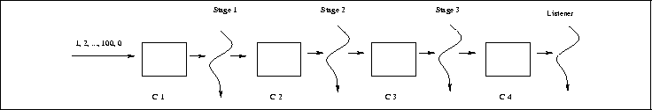
The code to be checked in this example implements a pipeline of
threads where each stage in the pipeline processes inflowing data and then
passes the transformed data onto the next downstream stage.
Figure 8 shows the basic structure of the
pipeline system whose code is contained in the file
PipeInt.java
in the tutorial examples directory.
Figure 8 shows that the pipeline has three processing stages
(threads) followed by a ``listener'' thread that simply receives the
incoming data and prints it to the screen. The data fed into
the beginning of the pipeline is generated in the main method
of the PipeInt class. The threads in the pipeline are connected
by instances of a Connector class. For this example, a
connector is a simple queue that can hold up to one integer.
Let's look at the actual code in
PipeInt.java
beginning with the main method of class PipeInt. After
the instances of all four threads (Stage1, Stage2,
Stage3, and Listener) and connectors are created, a
for loop places integers from 1 to 100 into the queue of
the first connector c1 by calling c1's add
method. Following the for loop, c1's stop method
is called. Examing the code for the Connector class shows that
this causes a 0 to be placed into the queue of
c1. Each of the stage threads considers an incoming 0
value to be a shutdown signal. Thus, if Stage number i
receives a 0 value from its upstream connector, it
(a) issues a stop on its downstream connector which causes
a 0 value to be placed in downstream connector's queue,
and (b) completes (i.e., shuts down). If Stage number i
receives a non-zero integer from its upstream connector from a call to
take on Connector number i, it grabs the integer,
increments it by 1, and puts it into the queue of the
Connector number i+1 via a call to the add method of
Connector number i+1. The Listener thread simply
takes the integers out of the last Connector's queue,
and when it receives a 0, the Listener shuts down.
Let's now consider how to use Bandera to see if the system satisfies a simple temporal property. In general, the methodology for rendering temporal properties in Bandera proceeds as outlined in Figure 5.5.1.
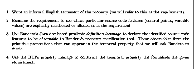
Figure 9: Methodology of property specification supported by Bandera