Sensor networking technologies have a wide range of military, medical, agricultural, environmental, and homeland security applications. Advances in sensor technology are making it possible to deploy a large number of sensors to monitor physical or environmental conditions, such as temperature, sound, vibration, pressure, motion or pollutants, at different locations. Before a sensor application is made operational, it must be tested and debugged, especially when it is used in a safety-critical system. This is often difficult to accomplish as sensor applications often have to be deployed in large, remotely located areas.
To address this problem, we have developed a reconfigurable test bed which is a collection of 18” x 36” plexi-glass boards. Each board has 8 TelosB wireless computing platforms (motes) which are connected via mesh networking to a gateway (Stargate Netbridge). The gateway can also communicate with the motes directly via a USB hub. The gateways of the various boards can exchange data with one another via TCP. Each board also has another board attached on top of it, on which E-puck robots can move. The PIR sensors on the TelosB can detect the presence of an E-puck.
The goal of this reconfigurable sensor test bed is to emulate different field scenarios in a lab so that the applications can be tested and debugged prior to actual deployment. Different scenarios involving fixed and mobile sensors to sense attributes such as temperature, light, motion, humidity and acceleration can be simulated in our lab. We have developed extensive software support for sensor applications on this test-bed which include remote monitoring and control of an application via a GUI, remote re-programming of sensors, and real-time data collection.
1. TeAMS and its various possible configurations
Figure 1.1 depicts the test bed structure and its various possible configurations. Gateways on the boards can be connected to form a mesh or tree or ring or star topology. Though in the figure, the gateways are shown to be connected directly, they are actually connected via a router to form any of these topologies. A configuration program creates desired TCP connection between various gateways.
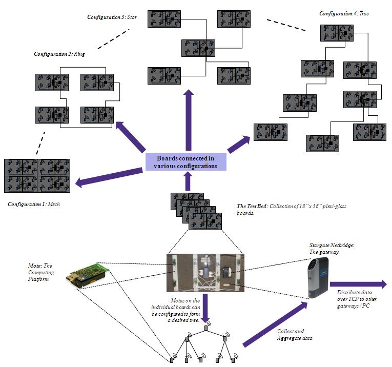
Figure 1.1 TeAMS structure and its various possible configurations
2. Software developed at PerSNL and deployed on TeAMS
For rapid development of applications, we have developed several software. They are:
Event Channel: Some motes produce some data, say temperature. Some motes need those data. Motes inform event channel that it will produce temperature by calling Publish Temp or it needs the data by calling Sub Temp. It is the responsibility of the event channel to transfer the data from producer mote to those which need that data.
GUI: Motes forming the network can be controlled by GUI individually. For example, if someone wants a mote to publish for temperature, he can do so by selecting appropriate mote from Mote Grid, then command from Commands list box and then clicking on Send Command button.
Modified Deluge: Mote can be reprogrammed wirelessly without connecting them to the computer.
Object Tracker: Motes are equipped with PIR sensors which can detect presence of a moving object. We put another transparent board on the top of each board so that ePuck can move over the motes. As ePuck moves over the motes, PIR sensor detects their presence and reports ePuck’s position to the base station.
We are constantly working towards enhancing these software. Figure 2.1 shows all PerSNL software in action.
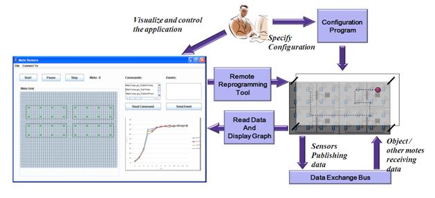
Figure 2.1 PerSNL software in action
3. TeAMS Construction
This Section discusses the various components and construction of TeAMS.
3.1 Components
Test bed was created using various hardware components. The components are listed below:
|
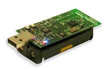
Figure 3.1.1 Crossbow’s TelosB motes |
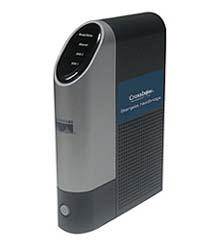
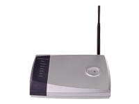
Figure 3.1.2 Crossbow’s Stargate Netbridges |
|
Figure 3.1.3 USB hub
|
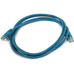
Figure 3.1.4 USB Cable
|
|
Figure 3.1.5 18" x 36" Plexi Glass board
|
Figure 3.1.6 Router |
|
Figure 3.1.7 Ethernet cable
|
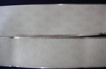
Figure 3.1.8 Velcro
|
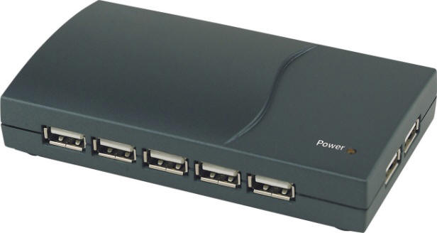
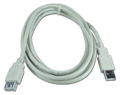
The test-bed uses 12 plexi glass boards. Each board is made up of 8 TelosB motes, 1 Stargate Netbridge and one 13 port USB hub. Thus, the test-bed consists of 96 motes, 12 Stargate Netbridges and 12 USB cables. Motes are powered using the USB hub via USB cables. A USB cable is used to connect the hub to a Stargate Netbridge’s USB port, thus each mote can be accessed by a C program running on the Stargate Netbridge. Stargate Netbridges on each board are connected to the router via an Ethernet cable. This allows the Stargate Netbridges to communicate each other via TCP connections.
3.2 Determining Board Size
We wanted to create a mesh of 96 TelosB motes in the lab. The maximum communication range of TelosB motes is around 75 meters -100 meters if there is no obstacle in between. We wanted 96 motes to communicate each other in a mesh and since the lab is very small, each mote will be able to communicate with every other mote and our purpose of creating the mesh will not be justified.
There are several interfaces provided by TinyOS, using which we can reduce the communication range of the motes. CC2420Control is one such interface. It provides a command SetRFPower (int range) We used this command to solve our purpose. By hit and trial experiments, we found that if we use SetRFPower(1), the two motes cannot communicate if placed more than 3-4 inches apart. In this case, the motes have to be placed very close to each other. We did not want that. We figured out that with SetRFPower(2), the communication range is 8-10 inches and with SetRFPower(3), the communication range is approximately 1 meter, which is very large. We decided to choose SetRFPower(2).
To create a 2 x 4 mesh of 8 motes, we required no more than 18" x 36" space. We decided to have 12 18" x 36" plexi glass boards and motes placed on them to create 12 2 x 4 meshes. This way, we can arrange these boards to generate different type of meshes according to the requirements of the application. These 12 boards are easy to carry and can be placed in the lab. They can be hung on the wall as well. By creating the test bed in the lab, we simulated a larger deployed network of motes in the lab.
3.3 Selecting Gateway
Once the board size was determined, the next task was to decide on the gateway to be used on each board. We have some Crossbow’s Stargate, which have WiFi. JVM is available for this platform which makes it easier to write TCP client/server application. Unfortunately, Crossbow stopped manufacturing Stargates and replaced them with a newer version, called Stargate Netbridge. It does not have Wifi; instead it has an Ethernet port. We could not find any JVM for this platform; however we could install C/C++ on it, thus we had to write TCP client/server application in C. By considering all these, we decided to use Crossbow’s Stargate Netbridge as a gateway on each board. We will use term gateway or node for Stargate Netbridge throughout the document. We also have HP some iPAQs which we are trying to make USB hosts. We are also studying Java on iPAQs so that in future, we can use them as gateways.
3.4 Creation of Test-bed
This section describes how these components are integrated together to form the test bed. The steps are as follows.
1. First we cut four Velcro of board size and stick them on the board shown
in Figure 3.4.2.
2. We then take 8 motes and stick Velcro on them as shown in
Figure 3.4.1.
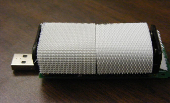
Figure 3.4.1 A mote with velcro
3. Stick the motes on the board as shown in
Figure 3.4.2.
4. Next, we take gateway and USB hub and stick them on the board using Velcro
as shown in Figure 3.4.2.
5. Finally, we attach motes to USB hub using USB cables, and connect USB hub
to gateway using USB cable.
6. Ethernet port of the gateway can be connected to the router using an
Ethernet cable, if required. By using the router and a set of C programs running
on gateway, we can create any topology for the gateways, either tree or ring or
any other according to the experiment to be performed.
7. Each of the gateways, USB hubs and router requires separate power supply.
8. A completed board without Ethernet cable and power supplies is shown in
Figure 3.4.2.

Figure 3.4.2 A complete board
Distances of the motes can be adjusted according to needs. The four Velcro can be moved up and down, the motes can be stuck anywhere on Velcro we want, thus providing us flexibility to adjust their position in any direction.
Figure 3.4.3 shows an experimental test bed of 48 motes created using 6 boards. It forms a mesh of 4 x 12.
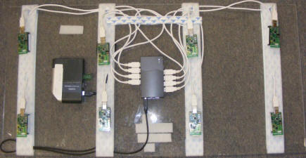
Figure 3.4.3 A 4 X 12 Mesh
3.5 Other Devices
Other devices, like Zigbee relays, as shown in Figure 3.5.1, can be attached to the boards. It can be glued to the board near the USB hub (This type of relay can be used as an actuator, if required in an application.)
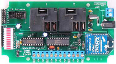
Figure 3.5.1 A ZigBee Relay
Nichols 16-A, Manhattan, KS 66506
Phone: (785)532-7842; Fax: (785)532-7353; Mailto: persnl@cis.ksu.edu