
![]()
![]()
![]()
![]()
![]()
![]()
![]()
|
|
|
|
Department of Computer and Information Sciences
Kansas State University
Graphical User Interface and Job Distribution Optimizer for a Virtual Pipeline Simulation Testbed
MSE PROJECT: Phase II
Major Professor: ……Dr. Virgil Wallentine Committee Members: Dr. Daniel Andresen Dr. Masaaki Mizuno Student: ……………..Walamitien Oyenan
November 7, 2003
Formal Requirement Specification 5. Formal Technical Inspection Check List
|
| Inheritance: JTree's implementation of pluggable
look and feel support and serialization is used without changes. The
UI-delegate implements the current look and feel, and serialization is based
on the Serializable interface, and XMLEncoder and XMLDecoder classes for
long-term serialization. | |
| Modification: The existing implementation of
in-place editing and rendering was modified to work with multiple cell types. | |
| Extension: JGraph's marquee selection and
stepping-into groups extend JTree's selection model. | |
| Enhancement: JGraph is enhanced with datatransfer,
attributes and history, which are Swing standards not used in
JTree.
| |
| Implementation: The layering, grouping, handles, cloning, zoom, ports and grid are new features, which are standards-compliant with respect to architecture, and coding conventions. |
2.2 - The Model
The model provides the data for the graph, consisting of the cells, which may be vertices, edges or ports, and the connectivity information, which is defined using ports that make up an edge's source or target. This connectivity information is referred to as the graph structure. (The geometric pattern is not considered part of this graph structure.)
![]()
Figure 1. A graph with two vertices and ports, and one edge in between
Figure 2. Representation of the graph in the DefaultGraphModel
2.3 - The View
The view in JGraph is somewhat different from other classes in Swing that carry the term view in their names. The difference is that JGraph's view is stateful, which means it contains information that is solely stored in the view. The GraphLayoutCache object and the CellView instances make up the view of a graph, which has an internal representation of the graph's model.
Figure 3. GraphLayoutCache and GraphModel
The GraphLayoutCache object holds the cell views, namely one for each cell in the model. The graph view also has a reference to a hash table, which is used to provide a mapping from cells to cell views.
2.4 - The control
The control defines the mapping from user events to methods of the graph- and selection model and the view. It is implemented in a platform-dependent way in the UI-delegate, and basically deals with in-place editing, cell handling, and updating the display. As the only object that is exchanged when the look and feel changes, the UI-delegate also specifies the look and feel specific part of the rendering.
In JGraph, the graph model, selection model and graph view may dispatch events. The events dispatched by the model may be categorized into:
| Change notification | |
| History support |
Figure 4. JGraph's event model
The GraphModelListener interface is used to update the view and repaint the graph, and the UndoableEditListener interface to update the history. These listeners may be registered or removed using the respective methods on the model.
The selection model dispatches GraphSelectionEvents to the GraphSelectionListeners that have been registered with it, for example to update the display with the current selection. The view's event model is based on the Observer and Observable class to repaint the graph, and also provides undo-support, which uses the graph model's implementation.
Most of the classes of the Pipeline Editor extend the classes of JGraph in order to provide a custom graph needed to draw the pipeline network. Only a few classes directly extend some Swing classes. The features implemented by the pipeline editor are described in the Software Requirement Specification document.
3.1 - Class diagram
Following is the class diagram of the pipeline editor:
Figure 5: Class Diagram of the Pipeline Editor
3.2 - Class description
This section describes each class of the pipeline editor ant its function. For the classes extending JGraph classes, only the purpose of the extension is explained. To understand the whole function of the class, it is necessary to refer to the extended class in the JGraph package.
Class Editor extends JPanel:
This is the main class representing the main panel of the application. It has
the graph panel (instance of JGraph) and the toolbars.
Class MyGraph extends JGraph:
Provide a custom graph model.
Contains all the necessary methods to create and insert custom components in the
graph.
Class MyMarqueeTransferHander extends
MarqueeTransferHander:
Provide a custom mouse handler for the graph.
Provide custom edges used to represent pipes.
Create popup dialogs.
Class MyModel extends GraphModel:
Define the criteria to accept the connection edge (pipe) and cell (component)
Class MyPortView extends Port view:
Define a custom representation of ports.
Class MyGraphTransferHandler extends
GraphTransferHandler:
Provide drag and drop support for the graph.
Class ButtonTransferHandler extends TransferHandler:
Transfert Handler for dragging the buttons from the toolbar.
Class DataCell extends DefaultGraphCell:
Define a cell use to display data from the simulation.
This cell is a JPanel.
Class DataRenderer extends VertexRenderer:
Use to render the DataCell as a JPanel containing information to be displayed.
Class MyCell extends DefaultGraphCell:
Abstract class for all the custom cells representing the components.
Each MyCell object has a reference to a DataCell.
Class CompressorCell extends MyCell:
Represent a component cell. The component is a compressor.
Each component cell has a DataCell and a MyUserObject to holds information about
the cell.
There is similar class for each component (Pipe, Joint, Split …).
Class CompressorView extends VertexView:
Define the shape of the component.
There is similar class for each component (Pipe, Joint, Split …).
Class MyUserObject extends Object:
Holds the property of the associated object (component) in a map for future
reference.
Display the property dialog for each component.
Class SaveServer:
Server to save the user file on the server side.
Receive the file via socket and save it.
Class SaveClient:
Send the file to be saved to the server via socket.
Class Optimizer:
Create JobComponent objects from component cells taken from the graph.
Each component cell has a corresponding JobCcomponent.
Holds a reference to BranchBound class to start the optimization.
Problem: Given a set of jobs with execution time and computation time and a set of machines, find the optimal job distribution among those machines. That is find the distribution that minimize the load of each machine.
4.1 - Depth-First Branch and Bound
Each job j has a computation weight Wj and a communication time Cj (sum of each communication time with all neighbors).
The objective is to minimize the load on the busiest machine.
At each node, we consider a cost function for the busiest machine only (worst-case estimate).
A vertex in the tree represents a partial/complete
allocation of jobs on machines.
The root of the search tree is the empty allocation.
A vertex at level k in the tree represents an assignment of jobs {J1,…,Jk}.
a) Cost function
The cost function f(x) is defined by:
f(x) = g(x) + h(x) ;
where:
g(x) : actual cost for the current allocation.
h(x) : load contribution on the busiest machine of the next job to be allocated.
We have:
| g(x) = ∑(Wj+Cj) for all j allocated to the busiest machine. |
Note: Cj consider only the communication with neighbors already allocated.
| h(x) = min(Wi, Ci) , i being the next job to be allocated. |
The heuristic function h(x) is explained as follow:
*If job i is eventually assigned on the busiest machine, its contribution to this node’s load is just its weight.
*If job i is eventually allocated on some other machine, its contribution to the node’s load is its communication time.
At each step, we want the take the case that minimize h(x).
b) Pseudo Algo:
minCost = infinity,
root = empty allocation,
cost(root) = 0
stack = allJobs
While stack not empty do
node = dequeue stack
if node isLeaf, update minCost
else
compute cost(node)
if cost(node) > minCost then prune node
else generate job allocation of all children of node
end if
end if
end while
return minCost
The following figure shows an execution of the Branch and Bound algorithm with 3 tasks (T1, T2, T3) and 2 processors (N1, N2) without and with pruning (Fig 7, 8).
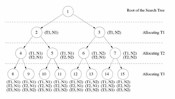
Fig. 6: Example with 3 tasks(T1, T2, T3) and 2 processors (N1, N2) without pruning
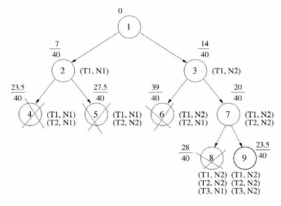
Figure 7: Example with 3 tasks (T1, T2, T3) and 2 processors (N1, N2) with pruning
c) Shared Version
In the shared version, the sequential algorithm is started. When there are enough nodes, the nodes are distributed among workers. Each worker can the start its own branch and bound algorithm. Every time a new bound is reached, it is compared to the shared bound and updated if necessary. At the end, the shared bound, which is the minimal found, will be associated to a solution object (containing the minimal allocation). This solution Object will be returned.
4.2 - Class Diagram
Figure 9: Class Diagram of the Optimizer
4.3 - Class Description
Class BranchBound
Implement the branch and bound algorithm.
Holds a reference to the current solution found.
Class Solution
Represent a solution to the Branch and Bound algorithm.
Contains the minimal allocation found.
Class Node
Holds the current allocation. The allocation can be partial (non-leaf node)
or complete (leaf node).
For a non leaf node, jobs non allocated yet are stored inside the node.
An allocation is an array of machine with their corresponding jobs.
Class Machine
Holds all the information about a machine.
Store all the jobs allocated to this machine so far.
Class JobComponent
Abstract class representing a job. Sub classes of this class are component
objects (pipe, compressor, joint…) .
Class Pipe extend JobComponent
Holds all the properties and initial values of a pipe.
There is a similar class for all components (Compressor, Joint, split…).
Class Worker extends Thread
Worker objects are threads searching a part of the tree.
They exchange new bounds via a shared memory (class SharedBound).
Holds a stack of nodes representing their part of the tree.
Class SharedBound
Holds the minimal bound found so far by the Worker objects.
Also holds the allocation (Solution object) corresponding to this bound.
Class CompareJob
Used to specify how jobs should be compared.
When the jobs are sorted, it helps reducing the number of nodes visited to reach
the solution.
Jobs are compared by number of neighbors and by weight.
References:
| Gaudenz Alder, Design and Implementation of the JGraph Swing Component |
http://www.jgraph.com/documentation.shtml
| Dar-Tzen Peng et al., Assignment and Scheduling Communicating Periodic Tasks in Distributed Real-Time Systems |
This document specifies the protocol between the GUI on the client side and the simulator on the server side.
The GUI needs to be able to listen to the simulator in order to get the data from the simulation. When the user wants to start a simulation, he needs to pass a filename to the simulator. If this filename is not valid, an error code is returned. If it is a valid filename (the file exist and has the proper format), then the GUI is ready to accept data from the server. As long as there is some data available, the server continues to send them. At any time, the user can interrupt the simulation. A message is then send to the simulator. The protocol will make sure that there is no lost of data due to interruption. The server can also send an end message when the simulation reaches the end. At the end (either by interruption, or normal termination), both the server and the GUI should be ready to start the protocol again.
The protocol is specify using Promela and check with Spin. We want to check that the protocol has no deadlock. We also want to be able to verify that there is no unexpected messages. (E.g. a data message when expecting an end message).
Following is the FSMs used to derive the Spin Model:

Figure 1: FSM for the GUI
Figure 2: FSM for the Simulator
SPIN Model:
/* Protocol GUI - Simulator
* Virtual Pipeline Simulation Testbed
*
* Walamitien OYENAN
*/
#define idle 0
#define wait 1
#define check 2
#define data_ex 3
#define recv_done 4
#define send_done 5
#define MAX 4
int datasent = 0;
mtype = {file, reject, accept, data, done}
chan socket1 = [MAX] of {mtype}
chan socket2 = [MAX] of {mtype}
proctype gui (chan send, recv) {
int state = idle;
end:
do
:: atomic { state == idle ->
send ! file;
state = wait;
}
:: atomic { recv ? reject ->
assert (state == wait);
state = idle
}
:: atomic { recv ? accept ->
assert (state == wait);
state = data_ex;
}
:: atomic { recv ? data ->
assert (state == data_ex || state == send_done);
skip;
}
:: atomic { recv ? done ->
assert (state == data_ex ||
state == send_done);
if
:: state == data_ex ->
state = recv_done;
:: state == send_done ->
state = idle;
fi
}
:: atomic { state == data_ex ->
send ! done;
state = send_done;
}
:: atomic { state == recv_done ->
send ! done;
state = idle;
}
od
}
proctype simulator(chan send, recv)
{
int state = idle;
end:
do
:: atomic { state == idle ->
recv ? file;
state = check;
}
:: atomic { state == check ->
send ! reject;
state = idle
}
:: atomic { state == check ->
send ! accept;
state = data_ex;
}
:: atomic { recv ? done ->
assert (state == data_ex ||
state == send_done);
if
:: state == data_ex ->
state = recv_done;
:: state == send_done ->
state = idle;
fi
}
:: atomic { state == data_ex ->
if
:: datasent < MAX ->
send ! data;
datasent++
:: else ->
send ! done;
state = send_done;
fi
}
:: atomic { state == recv_done ->
send ! done;
state = idle;
}
od
}
init {
atomic {
run gui(socket1,socket2);
run simulator(socket2, socket1);
}
}
SPIN Output:
(Spin Version 3.4.16 -- 2 June 2002)
+ Partial Order Reduction
Full statespace search for:
never-claim - (not selected)
assertion violations +
cycle checks - (disabled by -DSAFETY)
invalid endstates +
State-vector 56 byte, depth reached 53, errors: 0
162 states, stored
152 states, matched
314 transitions (= stored+matched)
330 atomic steps
hash conflicts: 0 (resolved)
(max size 2^19 states)
2.542 memory usage (Mbyte)
Reference:
“Spin Online References”, http://spinroot.com/spin/Man/index.html
The Software Test Plan (STP) describes the plans for testing the software. The purpose of the test plan is to ensure that the intended functionalities are implemented properly. To fulfill this objective, a series of test will be executed during the implementation.
This plan will address only those items and elements that are related to the GUI and the Optimizer of the Virtual pipeline Simulation Testbed. The primary focus of this plan is to ensure that the GUI provides the appropriate functionalities and that the optimizer produces an optimal solution.
The project will have three levels of testing, Unit, System/Integration and Acceptance. Unit testing focuses verification effort on the major functions, and integration testing tests the program structures built with unit-tested modules. The details for each level are address in the approach section and will be further defined in the level specific plans.
3. Test Item
These are list of items to be tested:
| Pipeline Editor | |
| Optimizer |
| Pipeline Editor functions | |
| Optimizer performance | |
| Communication GUI – Optimizer | |
| Communication GUI - Simulator |
There will be mainly two units: the GUI unit and the Optimizer unit. All the classes will be tested in the unit they refer to. Classes belonging to both units (JobComponent and subclasses) will be tested only in the GUI unit.
Once the individual units have passed unit testing those unit may then be used in integration testing. During integration testing, the units will be incorporated together and tested, adding one unit at a time. Integration testing will put together the GUI unit and the Optimizer unit.
6.1. Unit Tests
Pipeline Editor–
· Given a network, all operations as define in the Software Requirement Specification should produce the expected result.
· Drawing a network should meet all the requirements as define in the Software Requirement Specification document.
Optimizer –
· Given a set of jobs and machines, it should produce the correct output.
· Will have the capability to produce an optimal solution with at least 1000 jobs.
6.2. Integration Tests
GUI-Optimizer: Given a network, the GUI and the Optimizer should be able to communicate effectively and produce the expected file as output.
The system will pass if the functionality and performance requirements are met.
6. Suspension Criteria
Suspension Criteria: If any of the tests selected by the member do not give the expected result, then the testing will be suspended until the bug is fixed.
| Test Plan. | |
| Test Case Specification. | |
| Test input and test output data. |
The developer is responsible for all the testing activities.
Unit Testing – each unit will be tested during implementation.
Integration Testing – as the program units are integrated together, the program will be tested.
Approved by Committee Members.
Reference:
“IEEE Standard for Software Test Documentation”, IEEE Std 829-1998
The Implementation plan will define the tasks to be completed during implementation. The tasks are as following:
The Manual will describe all the features of the software (Pipeline Editor and Optimizer). It will also describe in detail how to use the pipeline editor. The completion criteria for this task would be when all the features and their use have been successfully described.
The architecture design will be revised every time a change occurs. These changes will be documented along with the component design.
The source code will be documented using the javadoc documentation. This source code will comply with the architecture design.
This assessment evaluation will contain a report of the tests done on the software and the results of these tests in the form of a test log.
The project evaluation document will review the process adopted for the implementation of this project and the effectiveness of the methodologies used. The completed software will be reviewed to check if it complies with the initial overview of the project. The product will also be reviewed to check the quality of the product.
The implementation of the software will be considered completed when
| The critical functions of the GUI will be implemented | |
| The optimizer will successfully compute the optimal distribution | |
| The GUI will successfully display the result of the simulation |
Formal Technical Inspection reports.
This document provides a formal checklist for the requirement specification document of the software. The purpose of this document is to ensure the quality of the software requirements. The checklist will be evaluated by three students and their report will be documented.
The Software Requirements Specification document (version 2.0) will be inspected.
| Padmaja Havaldar | |
| Sudershan Kodwani | |
| Liubo Chen |
Input: The Inspectors should review the SRS document and evaluate if Yes/No/Partial and suggest comments if needed.
Output: The inspectors’ reports.
Compatibility
| Do the interface requirements enable compatibility of external interfaces (hardware and software)? |
Completeness
| Does SRS include all user requirements (as defined in the concept phase)? | |
| Do the functional requirements cover all abnormal situations? | |
| Have the temporal aspects of all functions been considered? | |
| Does SRS define those requirements for which future changes are anticipated? | |
| Are all normal environmental variables included? | |
| Are the environmental conditions specified for all operating modes (e.g., normal, abnormal, disturbed)? |
Consistency
| Is there any internal inconsistency between the software requirements? | |
| Is the SRS free of contradictions? | |
| Does SRS use standard terminology and definitions throughout? | |
| Is SRS compatible with the operational environment of the hardware and software? | |
| Has the impact on the environment on the software been specified? | |
| Has the impact of software on the system and environment been specified? |
Correctness
| Does the SRS conform to SRS standards? | |
| Are algorithms and regulations supported by scientific or other appropriate literature? | |
| Does SRS reference desired development standards? | |
| Does the SRS identify external interfaces in terms of input and output mathematical variables? | |
| What is the rationale for each requirement? Is it adequate? | |
| Is there justification for the design/implementation constraints? |
Feasibility
| Will the design, operation, and maintenance of software be feasible? | |
| Are the specified models, numerical techniques, and algorithms appropriate for the problem to be solved? |
Modifiability
| Are requirements organized so as to allow for modifications (e.g., with adequate structure and cross referencing)? | |
| Is each unique requirement defined more than once? Are there any redundant statements? | |
| Is there a set of rules for maintaining the SRS for the rest of the software lifecycle? |
Traceability
| Is there traceability from the next higher level spec (e.g., system concept/requirements and user needs as defined in concept phase, and system design)? | |
| Does the SRS show explicitly complete coverage of requirements defined by client? | |
| Is SRS traceable forward through successive development phases (e.g., into the design, code, and test documentation)? |
Understandability
| Does every requirement have only one interpretation? | |
| Are the functional requirements in modular form with each function explicitly identified? | |
| Is there a glossary of terms? | |
| Is formal or semiformal language used? | |
| Is the language ambiguous? | |
| Does the SRS contain only necessary implementation details and no unnecessary details? Is it over specified? | |
| Are the requirements clear and specific enough to be the basis for detailed design specs and functional test cases? | |
| Does the SRS differentiate between program requirements and other information provided? |
Maintainability
· Does the documentation follow MSE portfolio standard
· Is the documentation clear and unambiguous
Verifiability/Testability
| Are the requirements verifiable (i.e., can the software be checked to see whether requirements have been fulfilled)? | |
| Is there a verification procedure defined for each requirement in the SRS? |
Clarity
| Are all of the decisions, dependencies, and assumptions for this design documented? | |
| Are names indicative of their meaning? | |
| Is each concept defined only once, with one clear meaning? | |
| Is each statement written as clearly as possible? |
Functionality
| Does the design implement the specification and requirements? |
Reliability
| Are abnormal conditions considered? | |
| Are the defect conditions/codes/messages specified completely and meaningfully? |
References
IEEE Std 1028-1998, “IEEE Standard for Software Reviews and Audits”. 1998 Edition, IEEE, 1983.
“Software Formal Inspections”, Software Assurance Technology Center (SATC), 1997, http://satc.gsfc.nasa.gov/fi/fipage.html
Weiss, Alan R. and Kerry Kimbrough, “Fundamentals of Software Inspections, Version 2.1”. 1995. http://www2.ics.hawaii.edu/~johnson/FTR/Weiss/weiss-intro