![]()
![]()
![]()
![]()
![]()
![]()
![]()
|
|
|
|
Department of Computer and Information Sciences
Kansas State University
Graphical User Interface and Job Distribution Optimizer for a Virtual Pipeline Simulation Testbed
MSE PROJECT: Phase I
Major Professor: …… Dr.
Virgil Wallentine
September 30, 2003
CHAPTER 2: Software Requirement Specification 2.2 User interface: Pipeline Editor 3.1 External interface requirements 3.4. Software system attributes CHAPTER 5: Architecture Elaboration Plan CHAPTER 6: Software Quality Assurance Plan 2.3 Roles and Responsibilities 3.2 Minimum documentation requirements 3.2.1 Software requirements specification 3.2.3 Formal Software Specification 3.2.4 Software design document 4. Standards, practices, conventions, and metric 7. Problem reporting and corrective action 8. Tools, techniques, and methodologies
CHAPTER 1: PROJECT OVERVIEW1. PurposeThe purpose of this project is to develop a virtual pipeline simulation testbed. The simulation will model the pressure and flow rate distribution of gas in a real pipeline system.
2. GoalsThe design and implementation goals are:
3. ConstraintsWhen developing a simulation, the main constraint is the time. The simulation has to run in a reasonable amount of time. For this reason, the software will use various parallel and distributed algorithms. Another constraint is the space constraint (memory). The project will take into consideration those constraints and will be designed to optimize the use of time and space.
CHAPTER 2: Software Requirement Specification
1. Introduction1.1PurposeThe purpose of this Software Requirement Specification is to establish and maintain a common understanding between the customer, Dr. Wallentine, and the software developer regarding the requirements for the proposed software.
1.2 ScopeThe proposed software is a GUI and a job distribution optimizer for a virtual pipeline simulation testbed. The software will simulate the pressure and flow distribution that is happening in a real pipeline system. The software will use various parallel algorithms on several machines in order to reduce the amount of time needed by this computing-extensive simulation. The software will also provide a GUI to graphically build the pipeline system and will perform the require computation in order to have a simulation as accurate as possible in a reasonable amount of time. The GUI will also be used to visualize the result of the simulation.
1.3 OverviewThis Software Requirements Specification (SRS) is organized into two main sections: overall description and specific requirements. The overall description section provides information describing general factors that will affect the requirements of the software. The specific requirements section describes in detail the requirements the software must meet.
2. Overall description2.1 Product perspectiveThe software is an interface to the Virtual Pipeline Simulation Testbed. It comprises a GUI (Pipeline Editor) and a job distribution optimizer (Optimizer). Once the pipeline system is drawn, the optimization and the simulation will be able start. The computation will be done on several powerful computers and result will be transmitted back to the GUI for display. Communication among cluster machines will be done by message passing and shared memory.
2.2 User interface: Pipeline Editora) The pipeline editor shall support drag and drop operations for drawing components (pipes, joints, and compressors). b) The pipeline editor shall support standard editing functions (copy, cut, paste). c) The pipeline editor shall provide zoom functions. d) The pipeline editor shall display the simulation results. e) The user shall be able to store/retrieve a previously drawn pipeline system (group of components called library) and connect it with some new groups or components. f) The user shall be able to move components inside the editor to have a better positioning. g) The user shall be able to edit the characteristic of each component displayed.
2.3 Hardware interfacesa) Each computer shall have enough memory and enough computing power (processors) to handle computing-extensive tasks. b) Each computer shall have an Ethernet card to communicate with other computers.
2.4 Software interfacesa) The cluster computers shall run under the Linux operating system. b) Each computer shall have the Java Virtual Machine installed (version 1.4 or later). c) Each computer shall have the JGraph 3.0 package installed.
2.5 Communications interfacesComputers shall support TCP/IP to communicate with each other.
2.6 Product functionsa) The product shall provide a GUI with all the components needed to draw a complete pipeline system, a button to start the optimizer and a button to start the simulation. b) The product shall provide an optimizer. The optimizer should be able to produce a job allocation that balances the load of each processor (that is, minimizes the load differences among cluster machines assigned to the simulation). The jobs are the pipelines components (pipes, joints, compressors …). Each job has some computation time and some communication time. The computation time depends on the characteristic of the component and the machine on which it is executed. The communication time depends on the amount of information exchanged and whether or not the connected component are on the same machine (local communication) or not (remote communication). Given these constraints, the optimizer will find an optimal distribution of jobs among machines that minimizes the workload of each processor. c) The product shall integrate a simulator. The simulator should solve a set of partial differential equations that mathematically models the pressure and flow rate distribution in each component of the real pipeline system.
2.7 User characteristicsa) Users of the system should be experienced pipeline design engineers who have a good understanding of a pipeline system. b) Users should be able to understand and manipulate pipeline characteristics. c) No particular training should be necessary to use the software. Following is the use case diagram for the software:
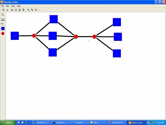
Virtual Pipeline Simulation System: Use Case 3. Specific requirements3.1 External interface requirementsThe interface provided will be the pipeline editor. The interface should provide all the necessary components to draw a complete pipeline system. Characteristics of those components shall be defined at the time of their creation. As the pipeline system can be very large, the interface shall provide a way to save/retrieve previously built pipeline subsystems. The interface will consist of one window with 2 toolbars and one menu bar. The horizontal toolbar will have a button for the components and will support drag and drop to insert components. The vertical toolbar will contain all the buttons for editing and zooming. The menu bar will offer the same functionality as the 2 toolbars in addition of the save/open function. The interface will offer the possibility to use the keyboard via some shortcut keys.
Following is a screenshot of a prototype GUI:
PIPELINE EDITOR
3.2 Functional requirementsIn order to provide the most realistic and accurate simulation, the system should implement adequately every features of the pipeline simulation. Each feature presents some required conditions that the system should meet to react correctly. The diagrams below show the sequence diagram and the interaction of the different parts of the software.
Sequence diagram of the Virtual Pipeline Simulation Testbed
Dataflow of the Virtual Pipeline Simulation Testbed
3.2.1 Pipeline EditorInputs: The input for the pipeline editor should come from the user. The user will define the components belonging to the pipeline system along with their characteristics. Outputs: The pipeline editor shall produce a list of component objects. A component can be either a pipe or a compressor.
a. List of componentsThe GUI shall provide the following components: pipes, station, split, joint, orifice meter, storage, compressor, driver, regulator, receipt point, delivery point.
b. Draw a componentThe user shall be able to draw any components needed for the pipeline system either by clicking on the component icon in the toolbar or by dragging it into the drawing pad. a) Draw a compressor A compressor shall only be connected to pipelines. It can accept several pipelines connections. b) Draw a joint A joint should be connected to at least two pipelines. Pipelines should be the only components connectable to joints. c) Draw a pipe Pipes should have another component connected at each end.
c. Delete a componentThe user shall be able to delete any components in the pipeline system either by right-clicking on the component and selecting remove or by clicking on the remove icon in the toolbar or using the delete key.
d. Edit a componentThe user shall be able to edit the characteristics of any components inside the pipeline system by using the right-click menu. Features available for editing should depend on the component selected.
e. Move a componentThe user shall be able to move any components of the pipeline system inside the drawing space using a dragging move. All the components connected to the component moved should also move and stay connected.
f. Undo/Redo an actionThe user shall be able to undo or redo any action done on any components of the pipeline system either by clicking on an icon in the toolbar. If there is no action to undo (or redo), the button should be disable.
g. Copy/Cut/Paste a componentThe user shall be able to copy, cut or paste any components of the pipeline system using the buttons in the toolbar or the standard keyboard shortcuts.
h. Zoom in/Zoom outThe user shall be able to zoom in or zoom out any area of the pipeline system using the buttons in the toolbar.
i. OptimizeThe user shall be able to launch the optimizer from the GUI by clicking on a button on the toolbar.
j. SimulateThe user shall be able to launch the simulation from the GUI by clicking on a button on the toolbar.
3.2.2 OptimizerInput: A list of components objects Output: A list of job objects. In addition to the fields of a component, a job has information about the machine on which it should be executed, the components connected to it, the execution time and the associated file containing the source code of its execution.
The job allocation optimization is a discrete optimization problem. The system will use the Branch and Bound algorithm to find the best distribution given some time and communication constraints. The solution may not be optimal but should be very close to the optimal one. The optimizer should adequately balance computation and communication time among all the processors. It should output a list of all jobs along with the machines on which they should be executed in order to have the best distribution.
3.2.3 SimulatorInput: A list of job objects Output: TBD The simulator should solve a set of partial differential equations to simulate the pressure and flow rate distribution in each component of the pipeline system. It should continuously output some values in order to visualize the current state of the simulation in the GUI.
3.3. Performance requirementsThe system should be able to handle at least a set of 100 jobs. The computation time should be kept minimal in both the optimizer and the simulator. The user should not wait more than 20 minutes to have the output of the optimizer and no more than 1 hour for the results of the simulator. The amount of data transferred should also be kept minimal to avoid too much communication overhead.
3.4. Software system attributesa. AccuracyAccuracy is the most important attribute for the virtual simulation pipeline testbed. The simulator must accurately model the pressure and the flow in each component of the pipeline system. If the convergence criteria are not well established, the simulation will be far from the real model.
b. ReusabilityThe system will have several releases with each time an increased number of functionality. Some new components and features will be added.
c. MaintainabilityThe system shall be separated into modules following the MVC (Model View Controller) pattern. There will be a module for the GUI, one for the optimizer and another one for the simulator.
d. PortabilityThe modules will be written in Java. As Java is supported on many platforms, it should be quite easy to move to another platform. For performance reasons, some parts will be written in some specific platform-dependant languages.
References IEEE STD 830-1998, "IEEE Recommended Practice for Software Requirements Specifications". 1998 Edition, IEEE, 1998. Dr. Scott Deloach’s CIS748 lecture notes “http://www.cis.ksu.edu/~sdeloach/748”
CHAPTER 3: PROJECT PLANThe project is divided into three phases, which are Specification phase, Design phase, and Implementation, Testing, and Documentation phase. At the end of each of those three phases, there will be a presentation.
CHAPTER 4: COST ESTIMATECost Analysis Using COCOMOThe COCOMO model is a good measure for estimating the number of person-months and the time required to develop software. The Virtual Pipeline Simulation Testbed can be considered as an organic mode process (in-house, flexible with less-complex development). The basic effort and schedule estimating formula is:
Effort = 3.2 EAF (Size) 1.05; Time = 2.5 (Effort) 0.38;
Where: Effort = number of staff-months EAF = Effort Adjustment Factor (cf. Table) Size = number of delivered source instructions (in thousands of lines of code)
The following table gives the value of the efforts multipliers. The product of those 15 factors will give the value of the EAF for the given project.
Software Development Effort Multipliers (EAF)
References:
CHAPTER 5: Architecture Elaboration PlanThe purpose of this document, as required by the MSE portfolio requirement, is to define the activities and actions that must be accomplished prior to the Architecture Presentation. The activities and actions to be accomplished prior to the architecture presentation are listed below: · Software Requirement Specification. · Software Quality Assurance plan · The Engineering Notebook · The vision document · The Cost Estimation · The Project plan · The Implementation Plan The artifacts that will undergo formal technical inspection are: · Object model · The interaction diagram
The Formal Technical Inspection will follow an IEEE standard formal checklist and will be led by two MSE students: 1. Padmaja Havaldar 2. Sudarshan Kodwani The inspectors will provide a well-documented report on the result of their inspection.
References: http://www.cis.ksu.edu/~sdeloach/748/protected/slides/748-4-formal-inspections.pdf
CHAPTER 6: Software Quality Assurance Plan1. PurposeThe software item covered by this SQAP is the ‘Virtual Pipeline Simulation Testbed’. The system is used to simulate the pressure ad the flow in the components of a real pipeline system. This SQAP covers the entire life cycle of the software.
2. Management2.1 OrganizationA committee of three professors will supervise the project. Only one developer will implement the project. The committee consists of:
The developer is Walamitien Oyenan. The committee will approve the design and requirements and will be responsible for monitoring implementation progress.
2.2 TasksThe following tasks will be completed for the project:
2.3 Roles and ResponsibilitiesThe developer will be responsible for all the tasks described above. He will be under the supervision of the major professor and will report to all the committee members in the form of three presentations.
3. Documentation3.1 PurposeTo ensure the quality of the Virtual Pipeline Simulation Testbed, as a minimum, the Software Quality Assurance will use the Software Design Document (SDD), the Software Requirement Specification (SRS), the Test Plan, the Formal Specification and the User Documentation for verifying and validating the product.
3.2 Minimum documentation requirements3.2.1 Software requirements specificationThe SRS lists the requirements of a system and it should correctly describe the system requirements. It specifies the functionality and performance of the project in terms of speed, reliability etc. It describes how the system interacts with the people using it and specifies the design constraints and standards to be followed.
3.2.2 Software Test PlanThe purpose of this document will be to develop and record formal procedures for the verification and validation of the pipeline simulation software.
3.2.3 Formal Software SpecificationA section of the software will be formally specified using a formal specification tool.
3.2.4 Software design documentThis document describes the overall structure of the software. It will contain an object model constructed using rational rose. The object model will describe the various classes used in the project.
3.2.5 User DocumentationThe user documentation will consist of a user manual, which will identify the features of the software and their functions. It will also describe all error messages and program limitations and constraints. The user documentation will also contain source code.
4. Standards, practices, conventions, and metric4.1 PurposeThis section identifies the standards, practices, conventions, and metrics to be used in the virtual pipeline simulation system and states how the compliance will be monitored and assured.
4.2 ContentThe MSE project portfolio will serve as a guideline in developing the documents. 4.2.1 Documentation StandardsThe Software Requirements Specifications (SRS) and SQA Plan (SQA) will be based upon IEEE Software Engineering Standards. 4.2.2 Coding StandardsThe source code will follow the guidelines in the Java coding standards. 4.2.3 MetricsThe COCOMO model will be used to estimate the effort and time needed for the development of the software.
5. Reviews and Audits5.1 PurposeThis section defines the technical and managerial reviews to be performed, and states how they are to be accomplished.
5.2 Minimum RequirementsA number of reviews will be done during the design, development, and testing of the project. They will be under the supervision of the committee. The following reviews will be conducted: · Software Requirements Review · Preliminary Design Review · Formal Technical Inspection
In addition, there will be three formal presentations at the end of each phase of development as describe on the project plan.
6. Testing and VerificationTo insure that the Virtual pipeline system meets the required quality, some tests have to be performed during the development process. The system must satisfy the standard functional requirements for the gasoline pump system stated in the SRS. The system should also satisfy the others criteria as stated in the SRS: performance, accuracy, reusability, maintainability and portability.
7. Problem reporting and corrective actionAll problems that cannot be resolved by the developer will be reported to the major professor. The committee will provide reviews on all current work and corrective measures for changes will be taken. The errors and problems encountered during the development of the project will be documented.
8. Tools, techniques, and methodologiesThe project will use the JGraph3.0 library along with Swing to build the Pipeline Editor (GUI). Rational Rose will be used to visually design the software being developed. Alloy or OCL will be used as a formal specification tool.
References
Walamiten Herve Oyenan Walamiten Herve Oyenan Walamiten Herve Oyenan Walamiten Herve Oyenan | |||||||||||||||||||||||||||||||||||||||||||||||||||||||||||||||||||||||||||||||||||||||||||||||||||||||||||||||||||||||||||||||||||||||||||||||||||||||||||||||||||||||||||||||||||||||||||||||||||||||||||||||||||||||||||||||||||||||||||||||||||||||||||||||||||||||||||||||||||||||||||||||||||||||||||||||||||||||||||||||||||||||||||||||||||||||||||||||||||||||||||||||||||||||||||||||||||||||||||||||||