Copyright © 2012 David Schmidt
Lecture 7:
Use cases and diagrammatic realizations
- 7.1 Use-case realization
- 7.2 Entity and method extraction
- 7.3 Communication diagrams
- 7.4 Sequence diagrams
- 7.5 Summary
When someone wants a machine built, they tell
us how they want the machine to behave when they use it.
They give us examples, and we develop the machine's structure and control
from the examples.
An example behavior is called a use case.
A use case is a "round of play" of a game, or a "session" with a tool,
or a "transaction" with a reactive system.
Example: a use case of a candy-bar vending machine goes like this:
-
(i) human inserts bill;
-
(ii) human presses button with picture of candy bar;
-
(iii) matching candy bar falls out of machine and onto floor.
7.1 Use-case realization
A use case describes behavior from the user's perspective.
But there is also behavior that occurs from the machine's perspective.
When we include the latter into the use case, we have a
use-case realization that gives us big clues how to build the
machine that has the desired behavior. For the candy machine, the
use-case realization might go like this:
- human inserts bill
-
The machine's bill slot rolls the bill under a scanner that checks
the authenticity and the value of the bill.
-
The value is transmitted
to the machine's money controller which enables the appropriate buttons for
the candy bars.
-
The bill drops in the money box.
-
human presses button with picture of candy
next to it
- The button-press event notifies the button's controller for the selected
candy bar.
-
The button's controller tells the data base to subtract the price of the bar
from the amount deposited, and it also
tells the candy-bar bin to release one bar
(which it does --- we hope!)
-
A signal is sent to the change-box controller to issue coins for change
(which it does --- we hope!)
-
Signals are sent to all button controllers to tell them to disable the
buttons next to the pictures of the candy bars.
-
matching candy bar falls out of machine and onto floor
The realization talks about entity objects,
both hard(ware) and soft(ware); multiple controllers for money and
buttons and change; and buttons and pictures of the view (boundary
entities).
With enough use cases documented and realized, we can design a machine
that does the behaviors.
When this technique is applied to a software system, it helps us
design the class diagram that lets us build the system.
Here is a
use-case realization of one round of a simulated Blackjack card game,
where a human plays against a "house player".
When writing the realization part, we should first think about which
"entities" will be part of the realization. For a card game, this
means Cards, a Deck, card Players, and a Dealer. The use-case realization
explains what the entities do:
-
human and house player gets two cards:
  for each Player p, both human and computerized:
    Dealer deals two cards from the Deck and gives them to   p
-
human is repeatedly asked if more cards are desired. Cards are dealt
till human says no or reaches 21 or "busts".
  for each Player p, both human and computerized,
      Dealer asks:
          while p wants a card and p's hand's score <= 21 :
              Dealer deals a card from the Deck and gives it to  p
-
human sees the results of how she and the house player played.
  for each Player p:
    p  shows its hand to the Dealer so that the Dealer can calculate
        the hand's score
-
human sees who won.
Dealer compares scores of all hands and announces the winner
How do we convert this verbal realization into a class diagram?
7.2 Entity and method extraction
The title says what we must do:
First,
we extract from our verbal descriptions the entities (sometimes called the analysis classes, but they are just class names)
that the software will need to operate, and we list the methods (sometimes called responsibilities)
that must be coded within the classes.
Example continued:
Look at the above use-case realization.
-
What are the entities? cards, deck, "hand", score, dealer, player,
win/loss total.
These entities are candidates for classes. (But not all --- the "score" of a hand is a function/attribute
of the "hand", so it won't be a class. Also, the win/loss total might be just
an int and not a class.)
-
Next, what are the actions/methods performed during a round?
wants a card, deals card from deck, player gets card, shows hand, dealer computes score,
announces winner. These are good candidates for methods for the classes.
We must assign each method to the class that has the "responsibility"
for doing the method.
-
Now, we list the classes with the methods and attributes/fields grouped
with them. For example:
-
class Player: has methods wantsCard?, getsCard, and
showHand
and will have an attribute for its win/loss total.
-
class Hand: computesScore of the cards in its hand.
-
class Deck: dealsAcard
-
class Dealer: maybe announcesWinner of a round; maybe playsRound
The above decisions are not final; they prepare us for diagramming
how the system behaves and for drawing a class diagram.
But we already have some useful ideas for mapping out an implementation
that computes the use-case realization.
7.3 Communication diagrams
Before we draw a class diagram, it is often helpful to draw a picture of how
the steps in our use-case realization are sequenced as
method calls from one entity to the next.
There are two standard diagram formats for drawing a use-case realization:
communication diagrams and sequence diagrams.
A communication diagram (also called a "collaboration diagram")
is an object diagram labelled by the
method calls that occur during a use-case realization.
Here is a simplified version of the previous use-case realization for a round of card play:
-
(1)
the Dealer gives two cards from the Deck to a Player and then
- (2) asks if the Player
wants another card. The Player says "yes", so another card is given.
The Dealer asks if the Player wants yet another card, and the Player says "no".
Then,
-
(3) the Dealer asks the Player for her Hand so that the Hand's score can be
used later to determine if the Player is the winner.
The diagram that shows the communications between Dealer, Deck, Player, and Hand
might go like this:
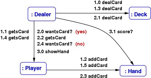
The labels on the arrows are method calls; for example,
1.0 dealCard states that as the opening action for (1) above,
the Dealer object calls the Deck object's dealCard() method --- so, we must define
method, dealCard, in class Deck, so that Dealer can call it.
The numbering lets you follow the sequence of calls
that realize the use case.
You use the objects and method calls
to design a class diagram whose classes and methods are capable of
executing the sequence in
the communication diagram.
And when you code a method that implements a round of play
(maybe we define a method, public void playRound() in class Dealer),
the code will follow the numbered steps in the communication diagram.
In this way, a communication diagram is almost
mapping out the code that we write
for the method in the controller.
You can always add more detail to the communication diagram, say, add the arguments
to the method calls and the answers that are returned (draw some back
arcs),
if this helps you better understand how to design the system.
What is shown above is the simplest form of communication diagram.
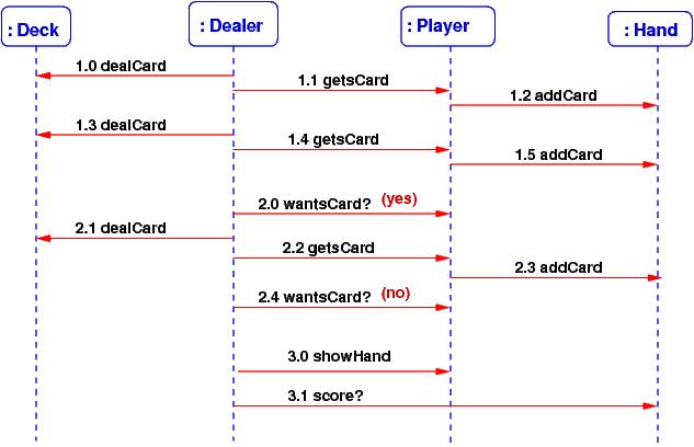
7.4 Sequence diagrams
A communication diagram can get crowded with lots of method calls on its arcs.
A sequence diagram shows the method calls
in a linear order --- many people find this easier to read. A sequence
diagram is also useful when there are tricky sequences
of calls (circular calls ("call backs"), iterations of calls, etc.)
Here is the sequence diagram for the above example:
Since there is more room to list the method calls, it is easy to label them
with their arguments and returned answers, like this:
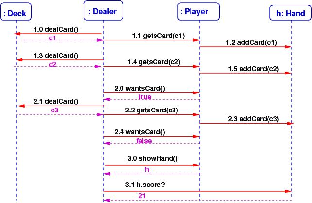
From a sequence diagram, you should be able to draw the communication diagram,
and vice versa. Either diagram tells you how to start drawing the class diagram.
7.5 Summary
Most software systems are variations on existing systems. But
when you are designing a new system, follow these steps:
-
Ask the user to describe how the system should behave (define the use cases).
-
Write the realizations that explain, in words, how the system will work internally
for the use cases.
-
Read the realizations and write down the names of the entities and actions that appear in the realizations --- these might
become the classes and methods in the system's class diagram.
-
Draw an object diagram that uses the entities that seems necessary to implement the use-case realizations.
-
"Test" the object diagram by labelling its arrows with the actions that are used in the use-case realizations --- this is a communication diagram.
-
If desired, draw the corresponding sequence diagrams.
-
Draw a class diagram.
References
Here are two OK references about communications and sequence diagrams:
-
https://www.lucidchart.com/pages/uml
-
http://sce.uhcl.edu/helm/rationalunifiedprocess/process/artifact/ar_desmd.htm
Exercise