The ending of the previous lecture should have you a little worried --- what is the best way to design a single-user reactive software system with "independent" subassemblies?
This question also worried the researchers at Xerox's Palo Alto Lab (PARC) in the 1970s when they wrote the first GUI-based systems in Smalltalk, a Simula67-like object language implemented on top of Lisp. (That last phrase has a lot of fate in it, as we will later learn....)
The Xerox researchers quickly learned that it was critical to isolate the assemblies so that there was independent development, containment of execution errors, smooth maintenance, and component reuse. The style of connectivity they used became known as the Model-View-Controller (MVC) software architecture. We will study it here.
Large software systems must minimize coupling so that compile errors and execution errors are limited in scope; components can be tested, plugged, unplugged, and replaced easily; and subassemblies can be saved and reused in subsequent systems.
Couplings are a key feature in modern software architectures. Here is an important case study:
Software systems like games, spreadsheets, and IDEs accept input from multiple sources and produce output to multiple windows.
A standard example is an IDE like Visual Studio: It consists of multiple windows (main window, edit window, toolbox window, solution window, and debug windows). Input is entered into all of these windows (text entry and mouse clicks), and input entered into one window can affect multiple other windows. (Example: you type the text for a label in the solution window, and the change shows in the solution window and also in the edit window. Or, you click "Start Debug" in the main window, and a breakpoint appears in the edit window and the call stack and local variables appear in the debug windows.)
It is a major problem coordinating input and output when there are multiple windows (Forms). We now study the architectures we might apply.
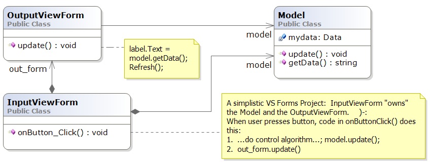
We consider the simplest version of this problem: A baby reactive toy uses a model, a controller, and two views (forms), one that accepts input and the other that displays output --- input entered into the input view causes computation on the model and generates changes to the output view, which displays information from the model.
This is bad. It is bad because the entire system lives in the Form that handles input events. How can one team (typically software engineers) develop the control and another team (typically graphical designers) develop the view when all of this is mixed into one file?!
How can the components be extracted for reuse in future systems? Why should a GUI with a button "own" the output form and the system's model (data base)? Will this architecture generalize to multiple forms where each form accepts input and shows output?
The above doesn't sound good, and the problem is that there is "too much"/"too strong" coupling (dependency). There is a simple way to measure "degree of coupling" of a class-diagram assembly, A, in terms of A's subassemblies:
(An edge in a subgraph is outgoing if it starts at a node in the subgraph and has an arrow to a node outside the subgraph.)
For the above architecture, V1, we have S(V1) = 3 and C(V1) = 3/3 = 1. That is, there are only 3 subassemblies (including the entire system) that we can extract and reuse out of this 3-component system. We can do better.
This is much better.
When you implement this architecture
in Visual Studio, construct and connect the InputView, Controller,
and Model objects
in the Main method of Program.cs. (For the above, the OutputView is
still constructed within the InputView, which owns it.)
Here's how to do it:
public void Main() {
   Model m = new Model();
   Controller c = new Controller(m);
   InputViewForm i = new InputViewForm(c, m);  // the input-view form will
                             // construct and own    new OutputViewForm(m)
    . . .
   Application.Run(i);  // give control to the input view
}
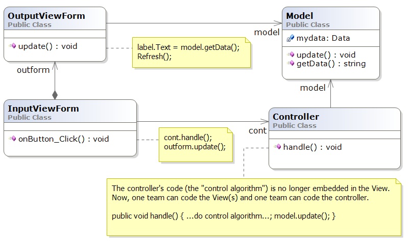
This is better --- the controller can be developed
independently from the views (although the controller depends on the model
and will need a dummy, "stub" model
at its early development stages).
This architecture makes it
easier to extract subassemblies for coding, testing,
and future reuse.
For this system, V2, we have S(V2) = 5 and C(V2) = 5/4 = 1.25, better than before.
It is still a problem that the input view owns the output view. When one view owns another, it causes cause trouble when we encounter systems that allow inputs into multiple views/forms.
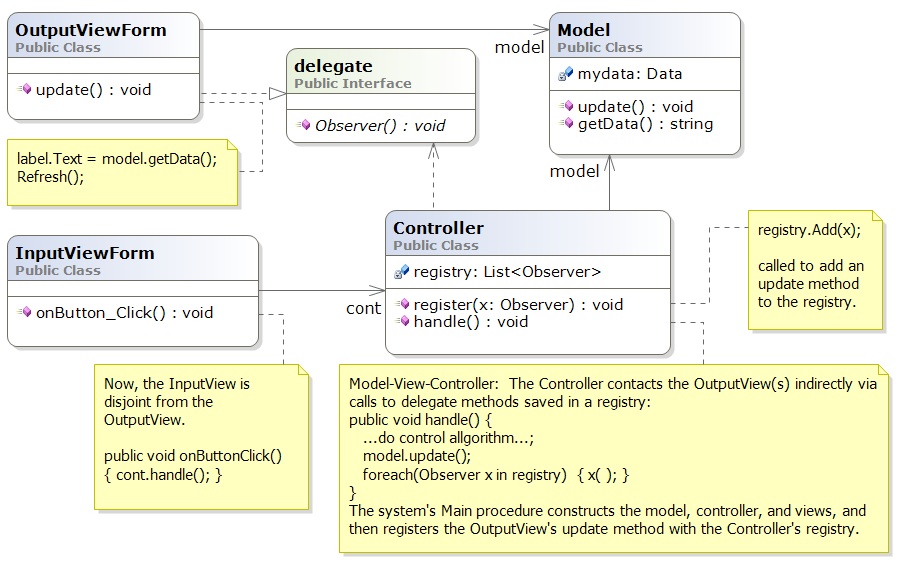
The novelty is the delegate declaration, which is a "method interface".
The output view's update method matches (implements)
the Observer delegate and it is registered with the controller, in its registry.
The Main method assembles the system and registers the Observer(s):
public void Main() {
   Model m = new Model();
   Controller c = new Controller(m);
   InputViewForm i = new InputViewForm(c);
   OutputViewForm f = new OutputViewForm(m);
   c.register(f.update);  // note that  f.update  has type  Observer
   ...
   Application.Run(i);  // give control to the input view --- it's now a reactive system
}
When the controller does a model update, all methods saved in
registry are called. So, the controller is not coupled to any view.
This makes it
easy to extend the system to have multiple forms (views) for inputs and outputs,
like a spreadsheet or IDE does. It is a standard technique in
systems building, maybe the most important one you will learn in this course.
For this system, call it, V3, we have S(V3) = 6, and C(V3) = 6/4 = 1.5, which shows improvement.
A variation on the above is to save the registry in the Model:
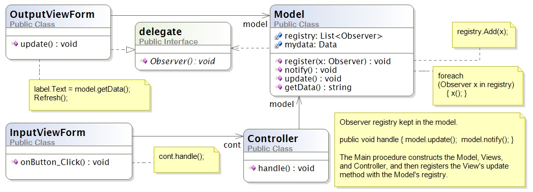
This arrangement is a bit less attractive because Model components ("data structures") are rarely written with registries embedded in them. (This flaw is repaired in Version 4, below.) But you might use the above in a special case, when you know that the Model assembly is finished and will not be embedded in a larger Model assembly.
We have almost minimal coupling of components in the system, which gives freedom for independent development, plug-unplug maintenance, and reuse and minimal impact due to component failure. (Can you see how to "decouple" the input view from the controller by using another delegate declaration?)
There is a variation on the above MVC architecture, which stores the delegate registry with the model in a super-class:
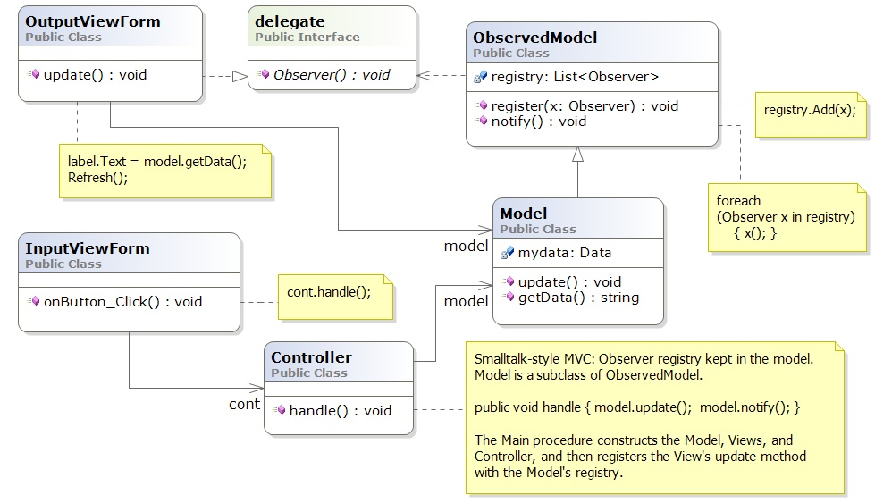
Now, the model component extends (is a subclass of) an ``observed model'', which is a class that holds the registry. This last pattern was the version of MVC developed by the Xerox PARC team and is often used. The diagram looks a little more complex than its predecessor, V3, and it shows in the measure of C: S(V4) = 7 (count carefully!) and C(V4) = 7/5 = 1.4.
The problem is that both the OutputViewForm and the Controller must connect to the Model and not to the ObservedModel --- If the ObservedModel and Model were "fused" into one, then C(V4) = C(V3).
So, why use the subclass arrangement? The Xerox people were already developing reusable libraries and learned quickly that some entity (model) classes were "observed" and some were not. Also, they worked with controllers that were simpler to write if the registry wasn't there. (The Xerox people programmed their systems in Smalltalk, which does not have delegate declarations!) So, the Xerox people put the registry code in a separate, reusable superclass. This little example shows that numerical measures like C don't tell the whole story about software architecture.
The key feature of MVC architecture is the "triad" or
"triangle topology" of assembly:
      IN/OUT Views
       |     \
       |      \
       |       \
       V        V
Controller ---> Model
Once again, here are some principles of MVC design
We will encounter more design patterns as we study more architectures.
     In&OutView           1. In&OutView calls Presenter with input event.
         |                2. Presenter computes answer, updates Model,
         V                   and queries Model for new values of data.
     Presenter               Presenter returns the new data values as
         |                   the answer to the call in Step 1.
         V                3. In&OutView displays the returned answer.
       Model
The architecture places a burden on the Presenter component, which both
implements the system's algorithm and knows exactly the data that
must be displayed. You will find this architecture in some business
systems, e.g., an ATM connected to a bank or a calculator tool ---
the output view shows just a single number or a single string.
Say we have a general-purpose output view, essentially a web-browser, that can show output formatted in some XML-like language. (XML is a "bracket language"; HTML is one instance of XML).
The controller not only signals the model to do updates, but it
then fetches updated data from the model and formats it as
an XML document. Then the output view fetches the XML document and displays it:
       InView  OutView
         |         |
         V         V
       Binder - ->delegate Observer
         |
         V
       Model
The controller is called a "Binder", because it does data bindings
of the model's data to names and layout in the XML document it builds:
When used for internet commerce, the InView and OutView are often merged together as a web browser or some XML/HTML-based viewer. The Binder is often a "proxy object" (we study this notion later) that was specially constructed by the Model and sent over the Web to the web browser to act as that browser's personal Binder. The Binder contains the "business logic" for doing the commerce transactions.
       In&OutView             1. View contacts Controller
       |        ^             2. Controller updates Model
       V        |             3. Model sends updated info to View
Controller --> Model
Beginners code reactive systems like this;
there is only one subassembly of this "circular" system!
Weaker coupling is good.
A system is strongly coupled if its components depend on many other components, meaning fewer subassemblies exist. Strong coupling is bad.
The coupling measure, C(A), of assembly A is not the final judge of A's quality, but as a rough rule, C(A) should be at least 1.0 --- otherwise, something is wrong if a component system cannot be untangled into as many subassemblies as there are pieces in the assembly. In such a case, there is no benefit from writing the assembly in pieces. (The underlying problem might be a lack of cohesion, which we study next.)
Say you have a reactive system that maintains two data structures (model/entity classes) A and B. The system has just one boundary class (view class) with one or more buttons. Sometimes, a button press triggers an update to data structure, A, and sometimes, a button press triggers an update to data structure, B. There are no relationships between A and B.
A simple implementation of the system would use one controller
that executes the A-update algorithm and the B-update algorithm:
                            +--> A
                           /
View --> ControllerForAandB
                           \
                            +--> B
This architecture, call it X1, is simple, but the controller is actually two algoriithms --- one for A and one for B --- unnaturally glued together; note that S(X1) = 5, and C(X1) = 1.25.
Since A and B are unrelated, so should be their controllers:
     +--> ControllerForA --> A
    /
View
    \
     +--> ControllerForB --> B
This architecture, call it X2, is better, because it exhibits
distributed control --- the update algorithms in the controllers
are married to the entities (models), not the view.
We have S(X2) = 9 and C(X2) = 1.8.
This is a reminder that
This small example should make us think about how large systems sometimes use algorithms that are naturally divided into pieces, depending on the data structures they use. This isn't exactly a radical idea --- the main reason for writing procedures/subroutines in a program is to divide up the algorithm into natural, understandable pieces.
We consider the development of controllers in a future lecture.
A component is cohesive if it is "about" one concept.
We can understand the notion by looking at coding style.
This class is "about" the concept of a playing card:
===================================================

public class Card {
    public readonly Count count;
    public readonly Suit suit;

    public Card(Count a, Suit b) { count = a;  suit = b; }

    public int BJvalue() {
      int i = (int)count + 1;
      if (i > 10) { i = 10; }   // in Blackjack, face cards have value 10
      return i;
    }

    public override string ToString() { return count + " of " + suit; }
}

===================================================
In generate, a
cohesive
class will manage one data structure, along with a few
primitive variables related to the structure:
===================================================

// This models one real-life entity:
class OneFormOfEntity {
    // there is a primary data structure that characterizes the entity:
    private ... oneDataStructureThatHoldsTheEntitysKnowledge;

    // additional fields might help maintain the data structure:
    private int aPrimitiveVarThatIsCountingSomething;

    // the constructor method initializes the fields:
    public OneFormOfEntity(valuesForInitializingTheEntity) {
      ... }

    // methods define abilities that the entity has
    //   (i) to say and do things and (ii) to learn things.
    // Each method uses most or all of the fields to do its work.
    public SomeProperty DoSomethingLookupSomething(....) {
      ... }

    public void LearnSomethingUpdateSomething(...) {
      ... }
}

===================================================
The class is about modelling one entity --- one
card player or one card or one spreadsheet or one text file or
one widget.
In contrast, a class that, say, defines both the structure of a playing card as well as the structure of a card deck has poor cohesion, because it is "about" two entities.
A cohesive component has fields that are referenced by almost all of its methods. Here is the "litmus test" that you use: a cohesive class cannot be rewritten into two separate classes without damaging (recoding) most of its methods.
If you like numbers, here is a formula for calculating a numerical score of cohesion:
H(D) = (m1 + m2 + ... + mM) / (F(D) * M(D))
===================================================

public class Card {
    public readonly Count count;
    public readonly Suit suit;

    public Card(Count a, Suit b) { count = a;  suit = b; }

    public int BJvalue() {
      int i = (int)count + 1;
      if (i > 10) { i = 10; }   // in Blackjack, face cards have value 10
      return i;
    }

    public override string ToString() { return count + " of " + suit; }
}

===================================================
H(Card) = (3 + 2)/(2*3) which equals 0.83 (because count is referenced
by 3 methods and suit is referenced by 2 methods). If you do some calculations,
you will find that well-written, "cohesive" classes have H-values near 1,
and non-cohesive classes (those that can be readily rewritten into
two classes without recoding many methods) have H-values less than 0.5.
The net result is that using a cohesive component in a system means the system will have weak(er) coupling --- the component does not cause a "cluster" of dependent components to form around it.
There is an area of experimental computing, called software metrics, that studies mathematical formulas for blueprints and code and applies the formulas to predict development times, maintenance costs, and "software complexity". You can look at the Wikipedia page for examples. (There are entries about how people have tried to measure coupling and cohesion in real-world systems. Good luck at understanding this stuff!)