Copyright © 2012 David Schmidt
Lecture 4:
Class diagrams
An object diagram is a "blueprint" of how storage is managed when a system
executes. It is similar to the "traffic diagram" an architect makes of a
building that shows the movement of people through the building while the
building is used.
But
an architect also makes a "floor plan" of the building, which shows the layout of
rooms, halls, and stairs that will be constructed for use.
A class diagram is a blueprint of the components needed
to build
an executing software system --- it is the "floor plan"
of the software system.
UML class notation is used to draw a class diagram. We use the variant
that is documented in the
Visual Studio lecture notes.
There is a related tool,
Nclass, which helps you draw
class diagrams and generate Visual Studio projects from them.
Nclass was used to make the diagram below. (There are more
in the VS Notes.)
Example
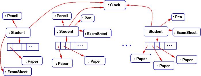
Say we are designing a computer simulation of students taking an
exam. The students bring some blank paper, and some pencils and pens.
At the exam, each student gets a question sheet;
all the students share (well, look at) the big clock at the front of the room.
The computer simulation must construct objects for the entities just described;
here is an object diagram of what the exam simulation might look like
while it is executing:
The object diagram gives big clues about what classes must be
written for the simulation.
Here is a class diagram that could
generate the above object diagram:
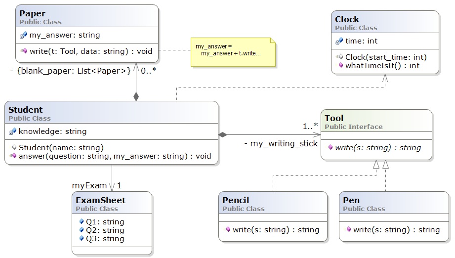
The meanings of boxes and arrows are documented in the
Visual Studio lecture notes.
Here is a quick summary:
-
The boxes represent entities: classes, interfaces, and code fragments (the latter can
also be comments).
Within a class box, the fields and methods are listed.
Within an interface box, the methods are listed.
-
The arrows define relationships. For the above example:
-
A solid arrow defines dependency (coupling): "A refers to B", or "A needs B to compile correctly" and "A retains a handle to B in a field."
-
The dashed arrow defines dependency also, but where there is not a field to remember the entity depended upon.
-
A solid arrow with a diamond at its base defines
composition: "A owns B" or "B is part of A" or "if A dies, so does B". This is a stronger form of dependency and occurs when A constructs B.
-
A dashed line with a white arrowhead defines realization: implementation of an interface.
-
The word label on a solid arrow gives the name of the attribute that is
declared within the class that depends on an entity, and the numerical-star
information states the "multiplicity" --- how many of the object are
remembered. Names of collections are enclosed in braces, and the - means
private.
There is a tool,
Nclass, which helps you draw
class diagrams and generate Visual Studio projects from them.
Exercise